2025-01-22Last updated
For Security Center to monitor and control the inputs of your Axis Powered by Genetec
unit, configure them in Config Tool.
Procedure
-
From the Config Tool homepage, open the Access control task, and
then click the Axis Powered by Genetec unit under the Access Manager role.
-
Click the Peripherals tab.
-
Expand the onboard interface, and then double-click the input to edit.
-
In the Edit Input dialog box, configure the following
settings:
- Name
- Input device name.
- Logical ID
- (Optional) Must be unique among all peripherals attached to the same unit.
- Shunted
- Select this option to ignore the inputs. Once shunted, the state of the input
remains at Normal, regardless how you trigger it.
- Contact type
- Set the normal state of the input contact and its supervision
mode.
Note: Only
door inputs and external inputs can be supervised.
- Not supervised and Normally closed
- The normal state of the input contact is closed, and the access control unit
does not report that the input is in the trouble state.
- Not supervised and Normally open
- The normal state of the input contact is open, and the access control unit
does not report if the input is in the trouble state.
- 4-state supervised and Normally closed
- The normal state of the input contact is closed, and the access control unit
reports when the input is in the trouble state.
- 4-state supervised and Normally open
- The normal state of the input contact is open, and the access control unit
reports when the input is in the trouble state.
For more information, watch the following video:
-
Click Save.
-
For supervised inputs, do the following:
-
Click the Hardware tab.
-
Scroll down to the supervised input and select one of the following settings,
according to your resistor values:
- ParallellFirst22k4k7
- The resistor values must be 4.7 kΩ and 22 kΩ.
- SerialFirst1k
- The resistor values must be 1 kΩ.
-
Click Apply.
-
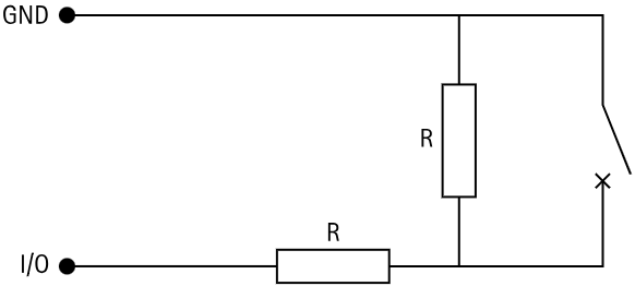
Install end of line resistors according the diagram corresponding to your resistor
values:
Parallel first connection:
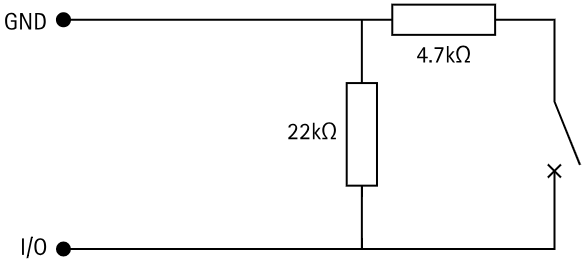
Serial first connection: